Please note the following points. Otherwise the synchronizer could be damaged.

  • Adjust the variable dampening valve of the needle before starting the engine. If the dampening of the needle is too low the movement of the needle could be destroyed.
  • Do not drop the gauges or expose them to shocks. Shocks may deform the mechanism.

The Boehm® synchronizer is equipped with a variable dampening valve to improve reading precision.
  • turning the outer dampening nut clockwise (cw) will increase dampening
  • turning the outer dampening nut counterclockwise (ccw) will decrease dampening
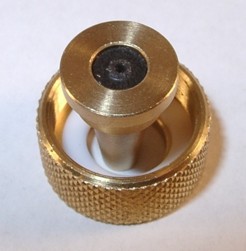
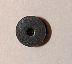
When you open the dampening valve, inside the hose connector you can see a small rubber disk (diameter 5 mm) with a very small hole (Figures 1 and 2). The air has to pass through this small hole and will be dampened.
The needle movement shouldn`t be dampened too strong because you don`t know whether there is no change of pressure or the valve is already closed. The rubber disc must be absolutely clean, no residues of oil and fuel. Residues will falsify the reading. Please also check also the rubber tubes for residues. Do not place the synchronizer underneath the carburettors. If you place the synchronizer above the carburettors, no fuel can flow into the rubber tubes


Before using the synchronizer you should verify that the tester is working accurately. Connect all gauges with Y-connectors and connect them to one carburettor (Figure 3). Now the same pressure is exerted on all gauges and they should show the same reading.
In case of deviation and if you have ordered the Boehm® synchronizer with zero-adjustment, you can recalibrate it yourself by using Torx 6 screwdriver. If not, you can send us the tester for recalibration.


zero-point adjustment of the Boehm® capsule pressure gauge
If you notice deviation between the gauges setting the deviation to zero is very easy. Connect the gauges by using the Y-set to one carburettor and start the engine. Remove the small plastic cap from the window and adjust the movement by using the Torx-6 screwdriver. Don`t forget to reinstall the plastic cap (Figure 4).

Dont`t place the synchronizer underneath the carburettors. Fuel and oil can drip into the ubber tubes and can contaminate the dampening valve. The best place for the synchronizer is on the seat. One rubber tube to the left and one rubber tube to the right of the bike (Figure 5). That way the synchronizer can`t hit the ground. The synchronizer is liquid-free and allows operation in any position.


How to connect the synchronizer with different types of motorcycle carburettors (Figures 6-10)
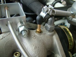
nozzle: You need no adaptors to connect the synchronizer; just remove the rubber cap from the nozzle. e.g. Kawasaki 4-cylinder, all BMW models since 1972, Yamaha XS 250-360-400-750-850-1100-1200, Laverda 500-750, Honda CBR 1000
tapped hole: In this case, you need special adaptors; e.g. all Honda models, Benelli, Ducati, Laverda 1000, Morini, Moto-Guzzi, MV, Yamaha XS 500-650.
You find the tapped hole at the carburettor or at the beginning, middle or end of the inlet manifold.
Our adaptors can be permanently installed if there is only a plug in the vacuum port. You needn`t install adaptors before every carb synchronization. Rubber caps are indluded to seal the vacuum.

How to connect the synchronizer with the carburettor or fuel injection of cars
If your car is equipped with WEBER dual carburettors, you will find the tapped hole behind the throttle butterfly. SOLEX dual carburettors normally use nozzles closed with a rubber cap. In some cases, there is a rubber tube from this nozzle to the advance mechanism of the ignition. By using the Y-connector, you can join the synchronizer as well as the advance mechanism with the carburettor.

Models of the BMW MOTORSPORT GMBH (M1, M3, M5) have one nozzle with a rubber cap for each intake manifold (Figures 11-12).

If there is neither a nozzle nor a tapped hole, we can offer you a special kit of adaptors, containing adaptor and rubber cap (Figure 13; Part number 10121). You have to tap a thread (M5x0.8) in the inlet manifold behind the throttle butterfly. Bond the adaptors with a thread locker.


You are an owner of a BMW R75 and the BING carburettor hasn`t any nozzles to connect the synchronizer? No problem. We have a special adaptor kit (Part number 10120) to solve the problem. BING has already prepared the carburettor for the adaptor (Figure 14). Drill through the centre hole with a 1.5 mm drill and assemble the adaptor by force fitting. A small hammer will help you.

Fueltank
On most of the bikes, the fuel tank has to be taken off. Otherwise you donīt gain access to the adjustment screws. You can place the tank onto the seat but if it falls to the ground, it will be damaged. It`s better to use our plastic fuel tank. Fill the tank with the fuel and when finished the balancing you can remove the fuel line very easy because it is connected with a quick-disconnect coupler. Our quick-disconnect coupler is hermetically sealed.
The fuel tank includes two plastic connectors with different sizes. GS5 (Part number 12007) has 5 mm diameter on both sides,

How to connect the synchronizer with a Rotax® 912 aircraft engine
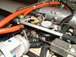
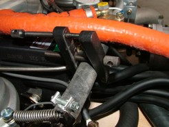
There are two possible connection methods to attach the synchronizer (Figures 15-17):
  • remove screw M6x1 from the intake manifold, insert adaptor M6x1 and connect synchronizer by using the rubber hoses.You have to remove or to squeeze the compensating tube. No exchange of air between the carbs is allowed
  • remove the compensating tube hose from the "push on connection". Connect the rubber tubes of our synchronizer with the "push on connection" by using our GRS 8-4 adaptor (Part number 12006) and a short rubber hose.
You will find more detailed informations on the german website which will be translated as soon as possible. www.boehm-synchrontester.de/anleitungrotax.html


How to synchronize?
Some will be satisfied to adjust the idle and mixture and call it done. However, those who strive for perfection will take the time to properly synchronize the carbs.
Before attempting to adjust the carburettors, you must have the other basic systems of the engine working properly:
  • ignition properly adjusted (timing spot-on, advance mechanism operating)
  • air filter clean
  • pollution line leak-free
  • valves adjusted
  • compression within specifications
Warm up the engine until it will idle reliable - without a choke. Connect the gauges with the carbs and adjust dampening of the needle. You don`t want to stop the needles but slowing them enough so that they`re readable. If one carb (or more) has a different reading from the others, there can be several reasons for it:
  • different clearance (play) of the throttle cables

  • different position of the throttle butterflies (different cross-sectional area of the throttle butterflies)

Your carbs are perfectly synchronized when the following conditions are fulfilled:
  • the throttle butterflies open simultaneously throughout their range of movement
  • same cross-sectional area of all throttle butterflies when idle
Keep in mind
  • opening the throttle butterfly will decrease vacuum, the needle will move cw
  • closing the throttle butterfly will increase vacuum, the needle will move ccw
It`s very easy to synchronize the carbs if they are equipped with a leverage because the throttle butterflies always open simultaneously. The throttles are fixed on a shared shaft with the aid of stop screws. Your only work is to synchronize the throttle stop screws. One carb is the master carb - it has no stop screw. All others have to be adjusted to match it.
The carb with less throttle opening will give a higher reading (e.g. 7,9" mercury the other one with 7,5" mercury). Gently turn that side`s carb`s throttle stop screw cw.
The carb with more throttle opening will give a lower reading (e.g. 7,5" mercury the other one with 7,9" mercury). Gently turn that side`s carb`s throttle stop screw ccw.

If idle is too high or too low, adjust idle with the master idle screw.
If the carbs are controlled by throttle cables, the procedure is a litte bit different but you will master the challenge as well. First, you have to loosen the throttle cable adjuster lock nuts and slack off the throttle cable adjusters until there is absolutely no tension on those cables. The next step is to synchronize the throttle stop screws as shown above.
Now the engine is running smooth at idle and we proceed in sychronizing the throttle cables. Only then, the throttle butterflies will open simultaneously. Increase engine speed by twisting the throttle grip in very very small steps. Watch the reading of the gauges. At first nothing happens. Why? Because there is still a slack in the cables. Continue twisting the throttle grip. Now that the free play in the cable is tensioned, affected carb starts to open its throttle butterfly. The other throttle butterflies remain on their idle position because they still have free play in their cables. You can easily determine that carb. Its needle will move cw (clockwise) , the other needles will move ccw. Remember!
  • opening the throttle butterfly will decrease vacuum, the needle will move cw
  • closing the throttle butterfly will increase vacuum, the needle will move ccw

conversion table
1 cm Hg = 0,0133 bar; Hg = mercury
1 cm WS = 0,00098 bar; WS = water
1 kPa = 0,01 bar; kPa = KiloPascal
1000 mbar = 29.53 " mercury = 75 cm mercury


Copyright © 2017 Boehm®